

PERMANENT ANCHOR CONSTRUCTION PROCEDURE
What is a permanent anchor? Let us explore the permanent anchor construction method together with Viet Nam Stay Structurers Construction Joint Stock Company – a member of Minh Duc Group.
PERMANENT ANCHOR CONSTRUCTION
The SSC-PA (Permanent Anchor) system is a type of permanent anchor that generates tensile frictional force. According to comprehensive surveys and practical applications, this type has been widely used worldwide for the permanent stabilization of slope embankments, uplift prevention, and particularly in hydropower and transportation projects. Its high quality is ensured through precision manufacturing in factory conditions and implementation in accordance with stringent construction standards. The system features a special protective layer against corrosion and oxidation, and it can also be applied for other purposes such as resisting uplift forces or buoyancy in foundation structures.
Permanent Anchor Construction Procedure
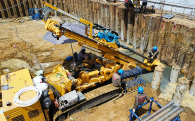
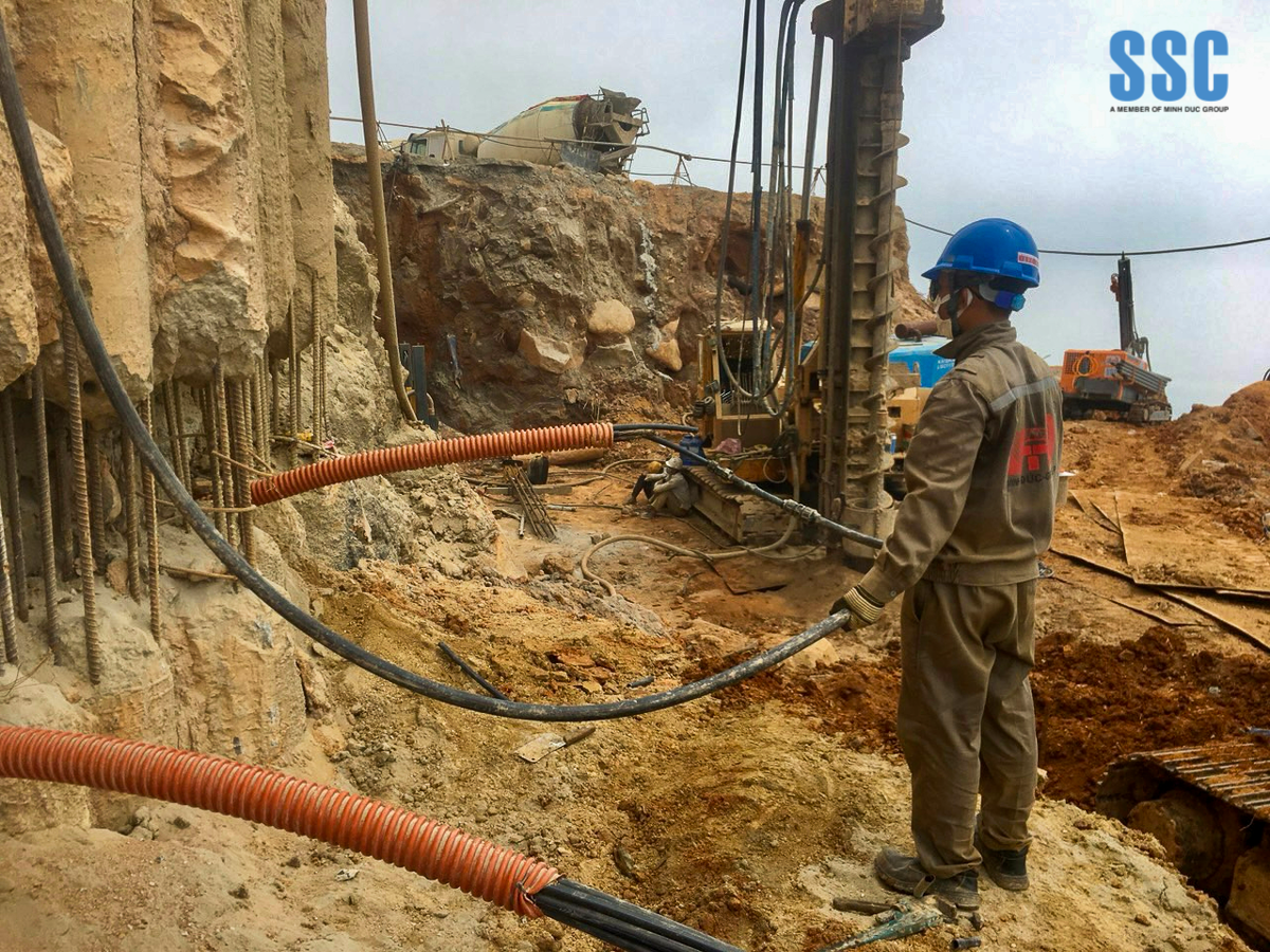
Drilling Boreholes
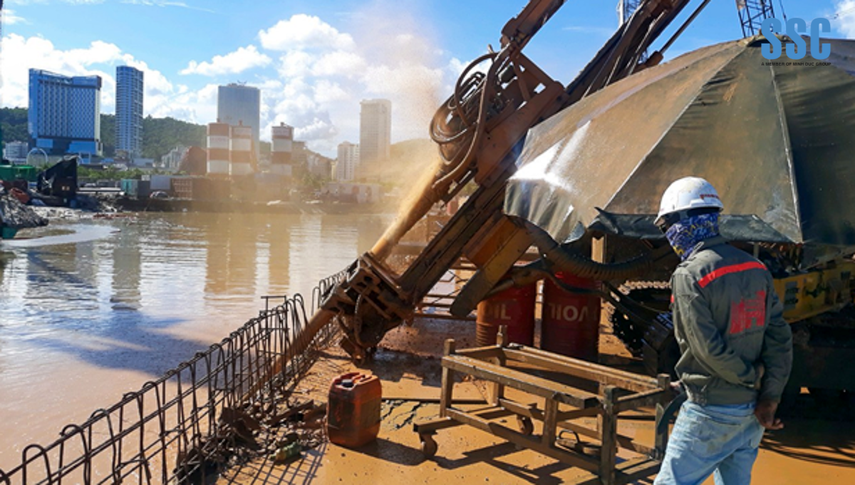
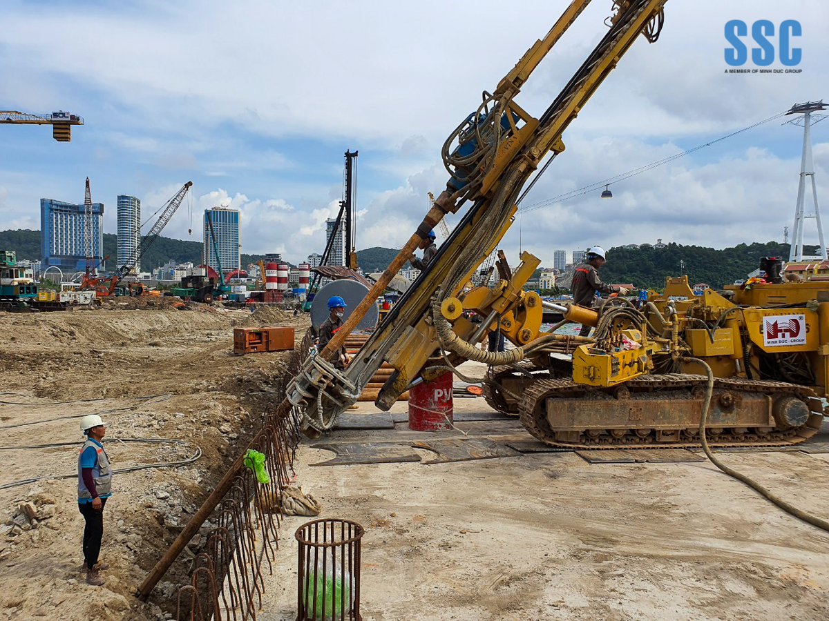
Percussive drilling and/or rotary drilling technology is employed to penetrate soft and loose soil layers. Temporary casing pipes are installed down to the base of weak soil layers that may cause borehole collapse and are removed upon completion of the installation process.
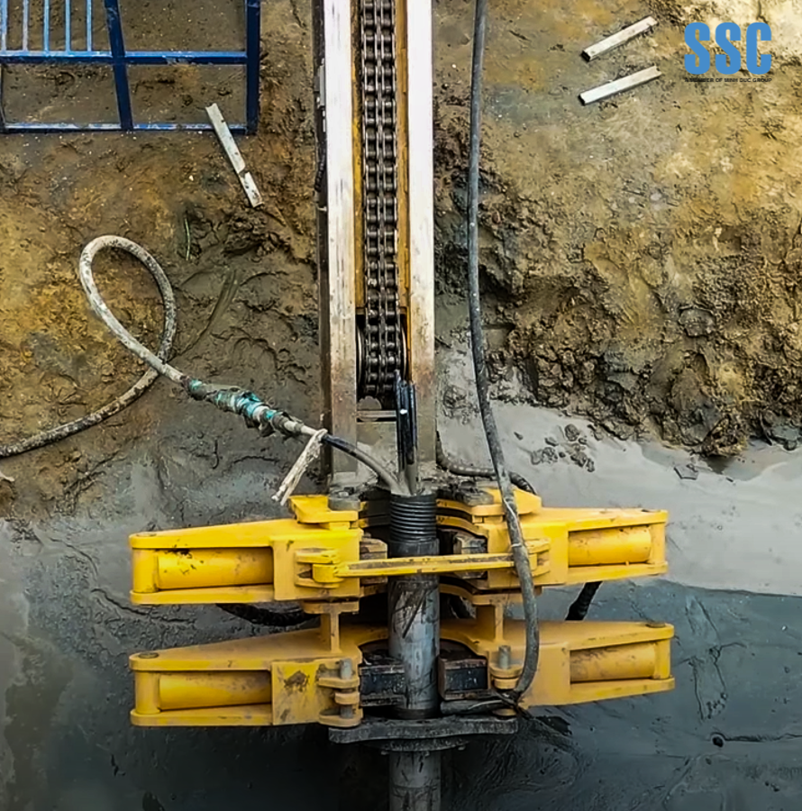
Rotary drilling technology, combining an inner drill rod and an outer casing, is also applied in cases where boreholes have a steep inclination angle, preventing drill cuttings from being discharged by conventional rotary drilling methods. In such cases, drilling is carried out according to the designed length and inclination angle.
When rock is encountered, appropriate drill bits and drilling methods are selected to suit the specific geological conditions.
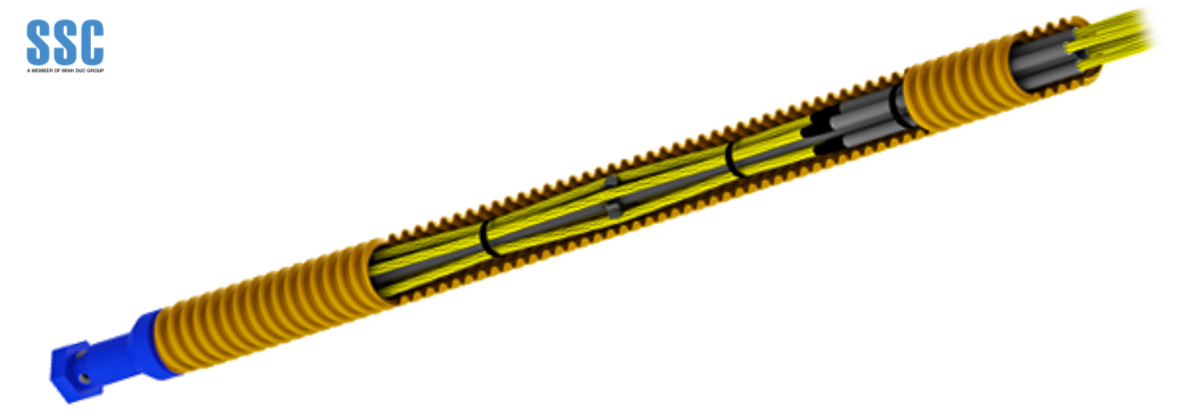
Permanent Anchor Fabrication: Learn more about Permanent Anchors here.
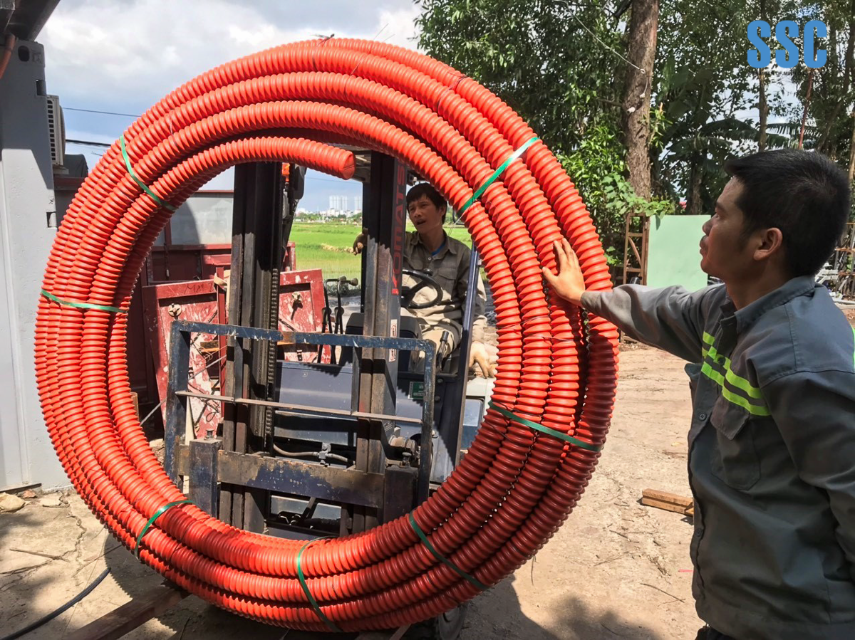
Ground anchors, as specified, are assembled in the workshop or fabricated at an on-site fabrication yard. Anchor heads and other structural components must be stored in warehouses using appropriate pallets or containers to protect them from weather and environmental conditions. Ground anchors must not be placed directly on the ground surface and must be provided with adequate protective measures to prevent damage to the anchor cables.
- All materials, including cables, grout, and anchor heads, must be tested in accordance with the project’s technical specifications and on-site regulations.
- Cable reels shall be lifted into the cable stand using a crane. The reels are placed on the ground at locations convenient for cable threading. The cable from the inner core of the reel is pulled out and fabricated into anchors.
- Prior to cutting the cables, the certification and inspection documents for each reel must be verified and cross-checked with the records kept in the project office.
- Cables shall be cut to the required length (including an additional 1 meter for tensioning purposes). Cutting cables with oxy-acetylene or similar thermal methods is strictly prohibited. The use of a disc cutter is recommended.
- The reel number and the number of strands in the cable line must be recorded in the “Cable Fabrication Report.”
- Fabricated cable bundles must be clearly identified with tags.
- The cable threading area shall be isolated with warning tape and warning signs at both ends of the cable line during installation to ensure that no unauthorized personnel enter the work area.
Permanent Anchor Installation
- In cases where drilling is carried out using a casing-supported drilling rig, the temporary anchor shall be lowered before the entire casing is withdrawn, and a sleeve grout layer shall be injected from the bottom up to the borehole mouth.
- The borehole length during drilling must be verified by the number of casing sections used, and the final borehole length after reaching the designed depth must also be checked before allowing anchor placement during the temporary anchor installation process.
- In cases where drilling is carried out using the DTH method or with an inner drill rod, the borehole length is determined based on the number of drill rod sections, including the drill rod connectors and the drill bit.
Grouting in Permanent Anchor Construction
The purpose of grouting is to provide grout along the entire length of the anchor bond zone. This process also helps stabilize the boreholes. Additionally, the grout fills any voids and displaces any water present in the borehole, if applicable.
Materials for Grout Injection
- Water: Only clean water shall be used.
- Cement: Portland cement type PCB 40.
- Additives: Non-shrink additives to enhance workability.
Grouting System
The mixer consists of a double-chamber tank for grout mixing and a holding tank to allow continuous grout agitation. The holding tank is connected to a pump located at the bottom of the double-chamber unit. The grout is then delivered to the pump. Grout shall be mixed properly in the tank for approximately 3–4 minutes until a uniform mixture is achieved. After mixing, the prepared grout is transferred to a high-pressure pump for injection into the anchor tube. A valve shall be installed between the pump and the anchor inlet.
Grouting Process for Permanent Anchor Construction
- Before grouting, the anchor grout pipe shall be inspected and, if necessary, flushed with clean water or compressed air to remove any debris.
- Water, cement, and required additives for grouting shall be prepared and readily available.
- Cement, water, and additives are mixed in the mixer’s mixing tank in the approved proportions. The mixture shall be prepared and blended until a uniform consistency is achieved. Once mixed, the grout is transferred for the pumping process.
- All grouting operations must be carried out to ensure complete grout filling.
- For permanent anchors, the grouting process is divided into two stages: Inner grouting (inside the corrugated sheath), Outer grouting (the grout layer surrounding the HDPE corrugated sheath)
Permanent Anchor Tensioning
- Tensioning shall not commence until the grout has achieved a compressive strength of 27 MPa, as specified in the design drawings, and the contractor has received written authorization from the client to proceed with tensioning.
- The validity of the Jack Calibration Certificate must be checked. If it has expired beyond six months, the equipment must be recalibrated before any field tensioning is carried out.
- Inspect the condition and operation of the hydraulic pump, jack, gauges, power supply, hydraulic hoses, and connectors to ensure the entire system is functioning properly prior to tensioning.
- The anchor bearing plate and bearing pad shall be installed directly onto the anchor guide pipe.
- Install the anchor head onto the bearing plate and place the wedges into the anchor holes.
- Position the hydraulic jack centrally above the anchor head, connect it to the pump and the pressure gauge.
- Verify the anchor setup on the jack with the working wedge positions at the rear, as applicable for temporary anchor works.
- Cable tensioning shall be performed in strict accordance with the specified tension force and sequence indicated in the approved drawings.
- Tensioning is carried out in four load stages (P): 25%, 50%, 75%, and 100% of the design load. These four stages must be executed continuously for each cable strand.
- If, during tensioning, the jack piston reaches its maximum stroke before achieving the initial load (P), the tensioning shall be paused, pressure released, the piston retracted, and tensioning resumed.
- The tensioning process shall follow these steps:
- Record the applied load and elongation of each strand in the “Ground Anchor Tensioning Report.”
- The load and elongation report shall be calculated, completed, and checked by the Project Engineer for temporary anchor works before submission to all relevant parties for approval.
12. The elongation of the cable is limited by the apparent length elongation as per BS1537:2000.
Δe = | Tension Load × Apparent Length |
Cable Cross-Sectional Area × Cable Modulus of Elasticity |
Where:
Lower-bound calculated length = 80% of the anchor free length + jack length
Upper-bound calculated length = anchor free length + 50% of the bond (fixed) length + jack length
Permissible tolerance for anchor elongation: ±6% (in accordance with TCVN 8870:2011).
Learn more about Vietnam Stay Structurers Construction Joint Stock Company – SSC: Here